Engine Update: Cascaded Shadow Mapping
Hello darkness, my old friend.
You ever play an older game and something feels off but you can’t place it? Half the time it’s the shadows. Or lack thereof. Our brains are weirdly good at detecting lighting inconsistencies. No shadows, no spatial grounding, no immersion. Just vibes of a PS2 cutscene.
Ray Tracing vs Shadow Mapping
In our deferred setup, what’s the best way to simulate shadows? Ray tracing is the most accurate, yielding the most impressive and realistic shadows. It traces rays from each point toward the light to see if anything blocks them. But those calculations are costly, and not suitable for all hardware. Shadow mapping is the more cost effective method, and can give great results with some tweaking.
Think about our deferred setup. We do a geometry pass to aggregate the information, then a lighting pass to use that information and make the final image. Before the lighting pass, how about we also do a pass to figure out the shadow information, and take that as another input to the lighting pass. Each light should make a texture of depth information from its view. Then we’ll sample them in the lighting shader.
Single Pass
Let’s start with what I just described, which is called single pass shadow mapping. The ShadowPass class, similar to the geometry pass class, just generates the framebuffers and textures for each light. We’ll support up to 16.
The real magic is in the shader code. When we’re looping over the lights, sample the shadow texture and compare the depths.
float getShadow(int lightIndex, vec3 worldPos) {
    vec4 lightSpacePos = u_lightViewProjs[lightIndex] * vec4(worldPos, 1.0);
    vec3 projCoords = lightSpacePos.xyz / lightSpacePos.w;
    projCoords = projCoords * 0.5 + 0.5;

    if (projCoords.z > 1.0) return 1.0;

    float closestDepth = texture(u_shadowMaps[lightIndex], projCoords.xy).r;
    float currentDepth = projCoords.z;

    float bias = 0.005;
    return currentDepth - bias > closestDepth ? 0.0 : 1.0;
}
Note the constant bias, that’ll be important later. We can then simply add this shadow into the rest of our light calculation.
Lo += shadow * (diffuse + specular) * radiance * NdotL;Here’s the result from this single pass implementation.
![]()
The shadows are there, but really harsh and pixelated. That’s called shadow acne. What can be done? Well, we can make the resolution of the shadow maps bigger. Right now, the resolution is dependent on screen size. This poses 2 problems. The resolution, but also the unnecessary resizing of the shadow maps every window resize. Let’s switch to a static shadow map size, like 4096.
That will help, but the finer grain edges will still be harsh. We can also use Percentage Closer Filtering, which basically blurs the shadow edges slightly. Just take some extra samples in the getShadow function.
float shadow = 0.0;
vec2 texelSize = 1.0 / textureSize(u_shadowMaps[lightIndex], 0);

for (int x = -1; x <= 1; ++x) {
    for (int y = -1; y <= 1; ++y) {
        float depth = texture(u_shadowMaps[lightIndex], projCoords.xy + vec2(x, y) * texelSize).r;
        shadow += currentDepth - bias > depth ? 0.0 : 1.0;
    }
}

return shadow / 9.0;
One more thing. The constant bias that I mentioned earlier. Let’s switch to a slope-scale bias to prevent peter-panning. You know, where your shadows detach and float away from objects like they’re off to Neverland. (Yes, that’s the actual term. No, I didn’t make it up.)
float baseBias = 0.005;
float bias = max(baseBias * (1.0 - dot(normal, lightDir)), baseBias * 0.5);
Looking better. Much more convincing.
Cascaded Shadow Mapping
So I’m feeling pretty good about myself at this point. Shadows working, PCF smoothing things out, bias dialed in. But look closer at Sponza. Look at the difference between the near and far shadows. Think about it, why do we have the same resolution for near and far shadows? We dont need as much detail on the far ones.
Let’s divide the frustum into sections, and make a different textue for each slice (or cascade). We’ll do 4 cascades. This requires a bit more setup on the cpu side.
Let’s do that frustum division. We’ll divide it up logarithmically.
float lambda = 0.75f;

float shadowNear = nearPlane;
float ratio = farPlane / shadowNear;

m_cascadeSplits[0] = shadowNear;

for (int i = 1; i <= NUM_CASCADES; i++) {
    float p = (float)i / (float)NUM_CASCADES;
    float log = shadowNear * std::pow(ratio, p);
    float uniform = shadowNear + (farPlane - shadowNear) * p;
    m_cascadeSplits[i] = lambda * log + (1.0f - lambda) * uniform;
}
Look at how this divides it up. Red is the closest cascade, yellow is the furthest
Building the Light Matrices
So we’ve got our split distances. But here’s the thing, each cascade needs its own view-projection matrix from the light’s perspective, sized to cover exactly that slice of the camera’s frustum. This is where it gets a little math-y. For each cascade, we need to:
- Figure out where that frustum slice is in world space
- Fit an orthographic projection around it (directional lights don’t have perspective)
- Do some sneaky stabilization so the shadows don’t shimmer when you move
Step 1: Get the frustum corners
We build a temporary projection matrix for just this cascade’s near/far range, multiply it with the camera view, then invert the whole thing. That lets us transform the 8 corners of NDC space (the cube from -1 to 1) back into world space.
Mat4 cascadeProj = perspective(fov, aspect, nearSplit, farSplit);
Mat4 cascadeViewProj = cascadeProj * cameraView;
Mat4 invViewProj = inverse(cascadeViewProj);

std::vector<Vec3> corners;
for (int x = 0; x < 2; ++x) {
    for (int y = 0; y < 2; ++y) {
        for (int z = 0; z < 2; ++z) {
            Vec4 pt = invViewProj * Vec4(2.0f * x - 1.0f,
                                          2.0f * y - 1.0f,
                                          2.0f * z - 1.0f, 1.0f);
            corners.push_back(Vec3(pt) / pt.w);
        }
    }
}
Step 2: Bounding sphere, not bounding box
Your first instinct might be to fit a tight axis-aligned box around those corners. Don’t. A tight box changes size as the camera rotates, which makes your shadow map coverage wobble and your shadows swim around. Ugly. Instead, use a bounding sphere. Spheres don’t care about rotation. Find the center of the frustum slice, then find the radius that encompasses all 8 corners:
Vec3 center(0.0f);
for (const auto& corner : corners) {
    center = center + corner;
}
center = center / 8.0f;

float radius = 0.0f;
for (const auto& corner : corners) {
    radius = std::max(radius, length(corner - center));
}
radius = std::ceil(radius); // Round up for stability
Step 3: Texel snapping
Even with a stable sphere, you’ll get shimmering as the camera moves sub-texel amounts. The fix: snap the light’s position to the shadow map’s texel grid.
float texelsPerUnit = (float)SHADOW_MAP_SIZE / (radius * 2.0f);

Mat4 lightView = lookAt(center - lightDir * radius, center, up);

Vec4 shadowOrigin = lightView * Vec4(0, 0, 0, 1);
shadowOrigin = shadowOrigin * texelsPerUnit;
Vec4 rounded = Vec4(std::round(shadowOrigin.x),
                    std::round(shadowOrigin.y),
                    shadowOrigin.z, shadowOrigin.w);
Vec4 offset = (rounded - shadowOrigin) / texelsPerUnit;

lightView[3][0] += offset.x;
lightView[3][1] += offset.y;
Step 4: Extend the depth range
One last gotcha. Shadow casters might be behind the camera but still cast shadows into view. We extend the orthographic projection’s depth range way back to catch them:
Mat4 lightProj = ortho(-radius, radius, -radius, radius,
                       -radius * 4.0f, radius * 4.0f);
The 4.0f multiplier is pretty generous. You could tune it down if you know your scene’s bounds, but overshooting doesn’t cost much.
So now we’re ready to actually use the shadows.
int getCascadeIndex(float viewDepth) {
    for (int i = 0; i < NUM_CASCADES; i++) {
        if (viewDepth < u_cascadeSplits[i]) {
            return i;
        }
    }
    return NUM_CASCADES - 1;
}

float getShadowCSM(int lightIndex, vec3 worldPos, vec3 normal, vec3 lightDir, float viewDepth) {
    int cascadeIndex = getCascadeIndex(viewDepth);
    int shadowMapIndex = lightIndex * NUM_CASCADES + cascadeIndex;

    vec4 lightSpacePos = u_lightViewProjs[shadowMapIndex] * vec4(worldPos, 1.0);
    vec3 projCoords = lightSpacePos.xyz / lightSpacePos.w;
    projCoords = projCoords * 0.5 + 0.5;

    if (projCoords.z > 1.0) return 1.0;

    // Slope-scaled bias - smaller for closer cascades
    float baseBias = 0.005 * (cascadeIndex + 1);
    float bias = max(baseBias * (1.0 - dot(normal, lightDir)), baseBias * 0.5);

    float currentDepth = projCoords.z;

    // PCF
    float shadow = 0.0;
    vec2 texelSize = 1.0 / textureSize(u_shadowMaps[shadowMapIndex], 0);

    for (int x = -1; x <= 1; ++x) {
        for (int y = -1; y <= 1; ++y) {
            float depth = texture(u_shadowMaps[shadowMapIndex], projCoords.xy + vec2(x, y) * texelSize).r;
            shadow += currentDepth - bias > depth ? 0.0 : 1.0;
        }
    }

    return shadow / 9.0;
}
and we can see the cascade overlay onto the scene
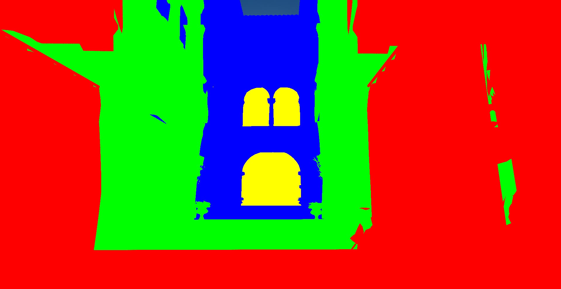
 Super helpful debugging view. You can see there’s something wrong with the shadows in green and red bands. They’re missing. This is almost always related to the math of fitting the bounds around the cascade. I also adjusted the light to hit the wall for more of an interesting light view.
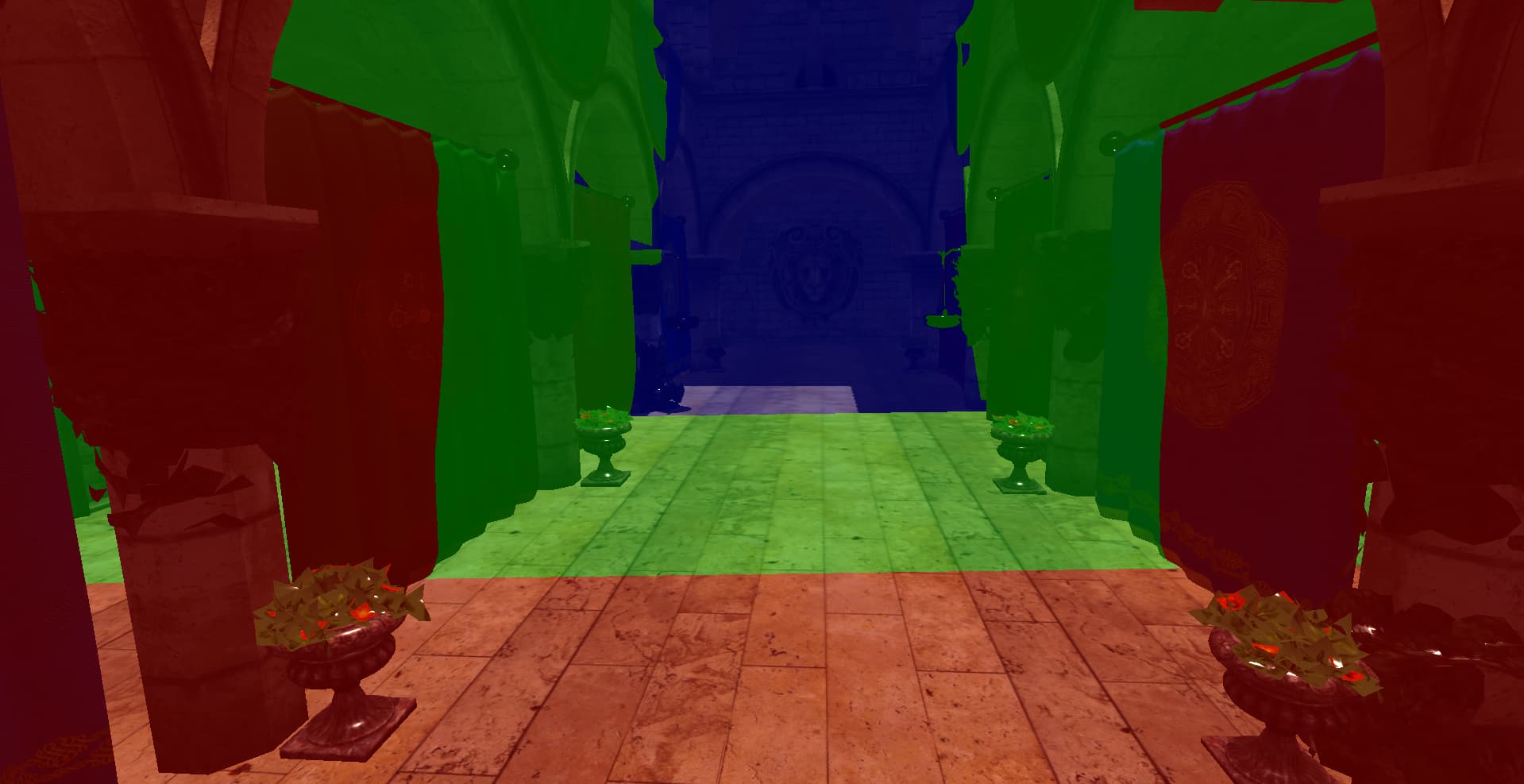
Look at these final results, and the shadows behind the banners
And there we go. Cascaded shadow mapping in the engine. It’s not the most sophisticated implementation (no cascade blending yet, so you can catch the seams if you look for them), but the difference from single-pass is night and day. Pun intended. Next up, maybe soft shadows or variance shadow maps. Or I’ll get distracted by something else entirely. That’s how engine dev goes.